
Accumulator
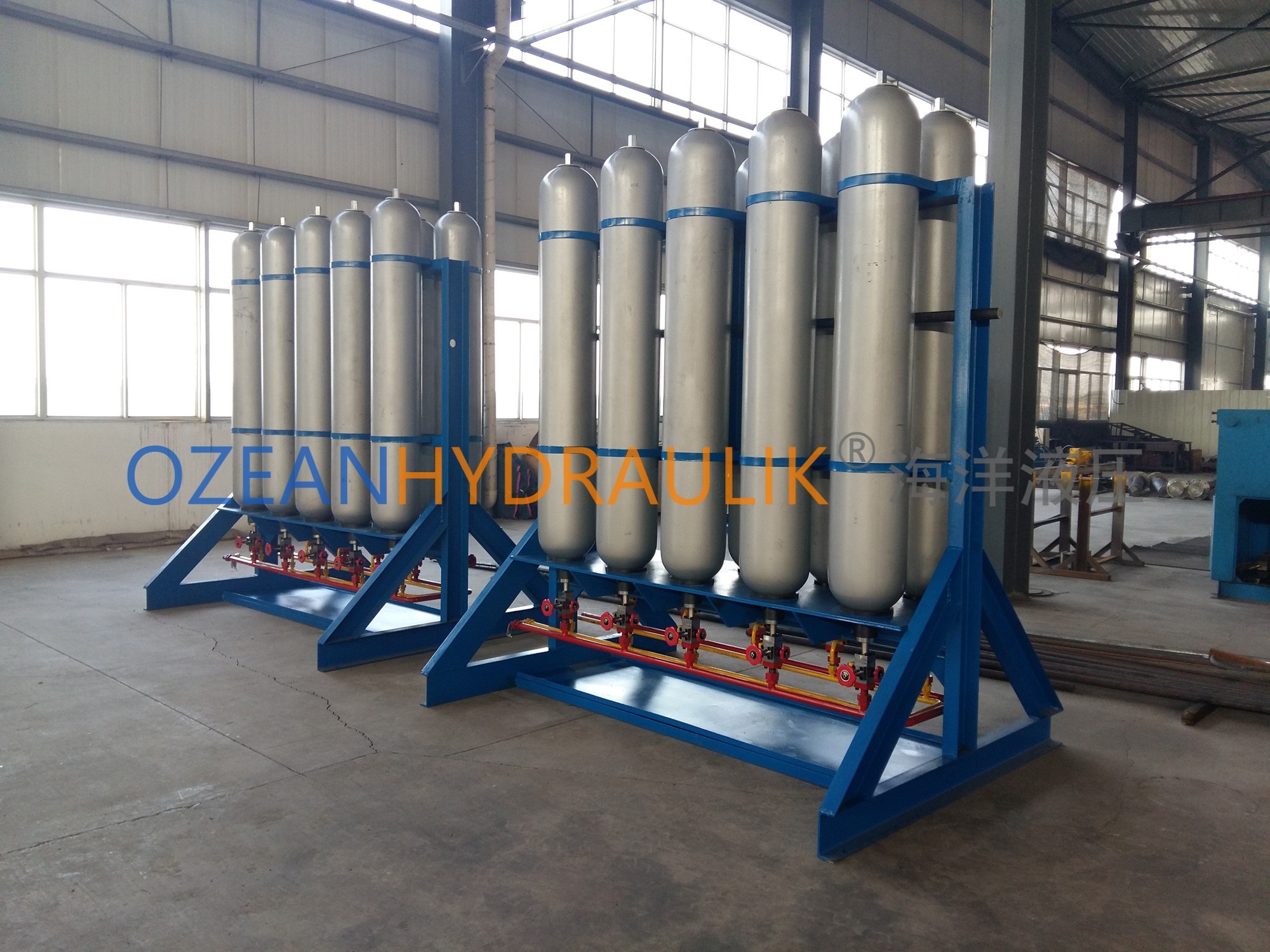
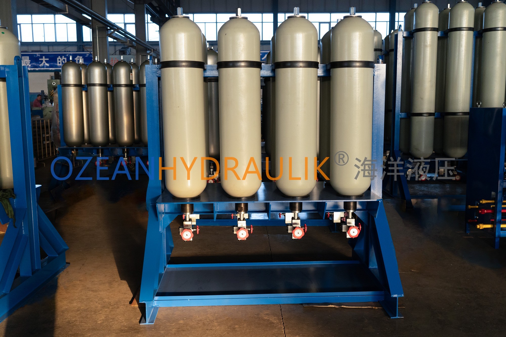
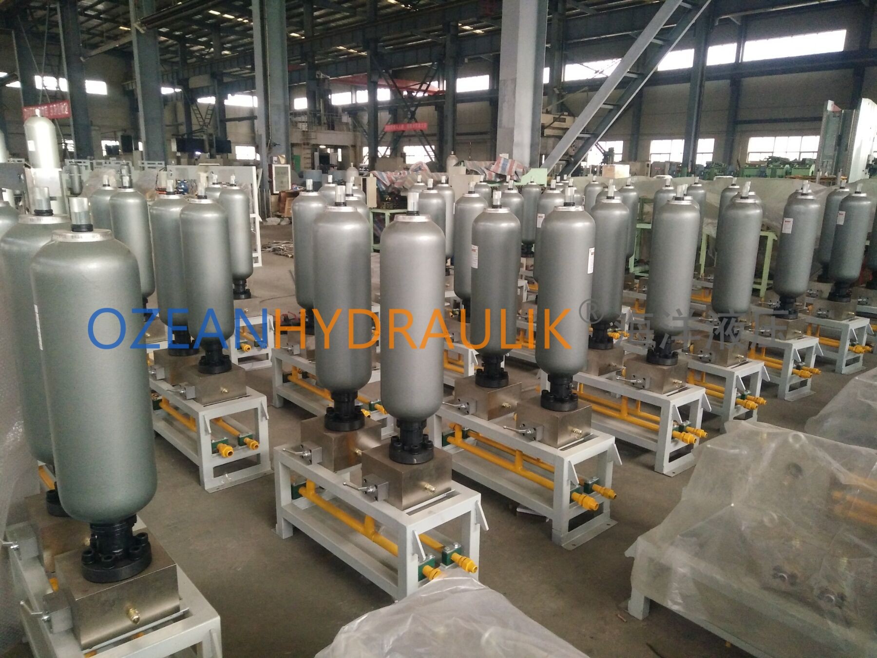
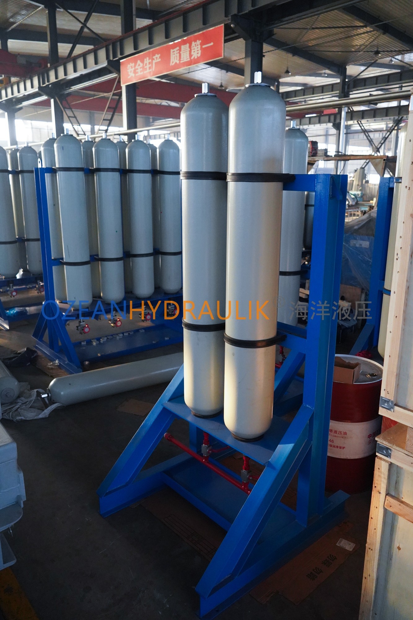
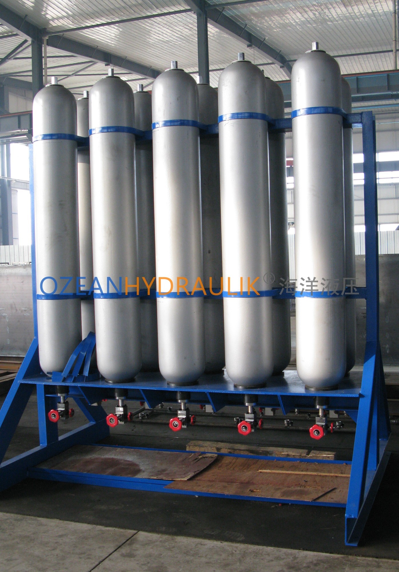
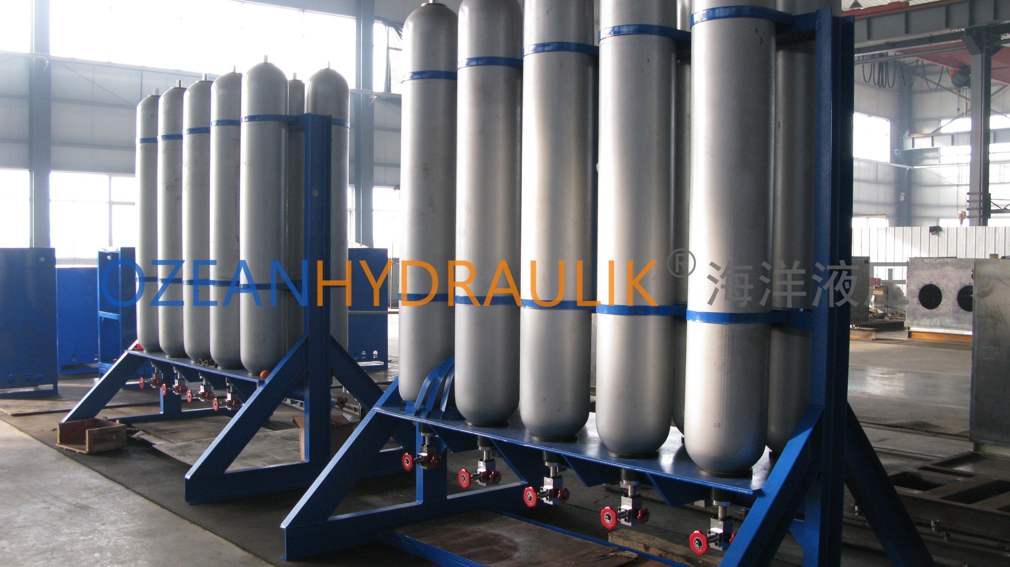
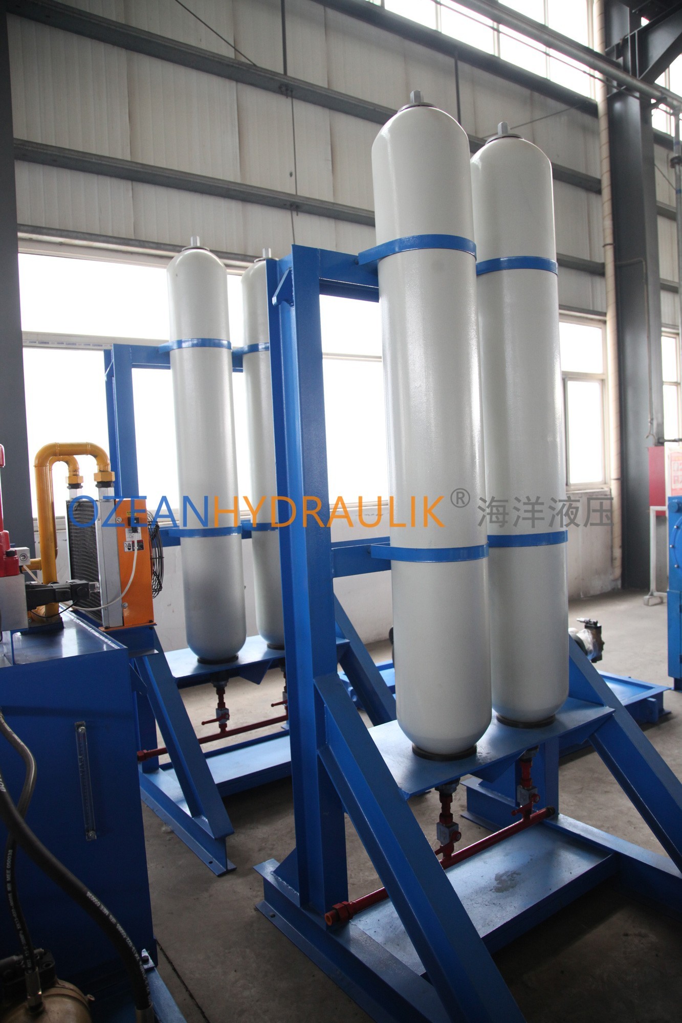
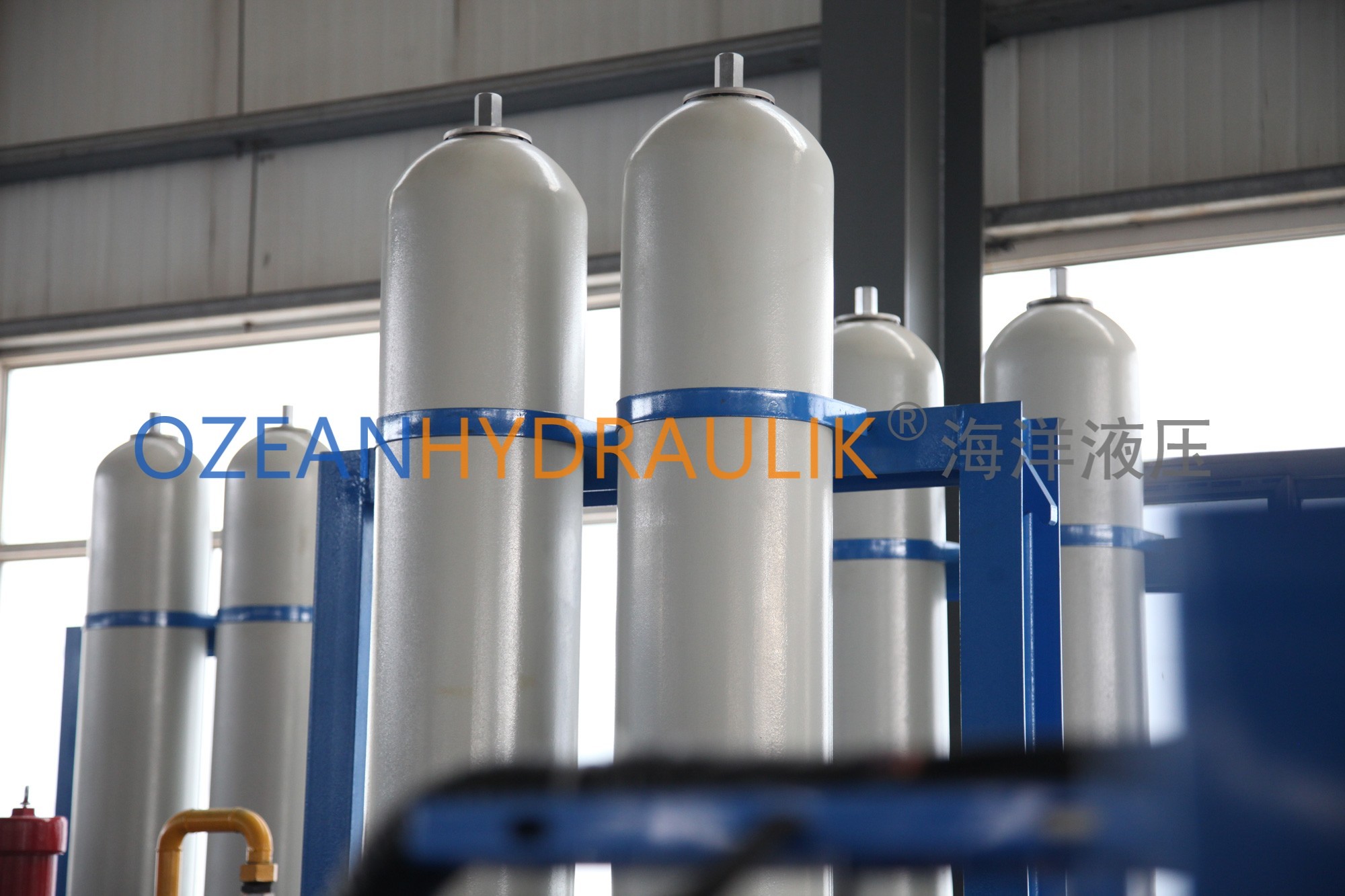
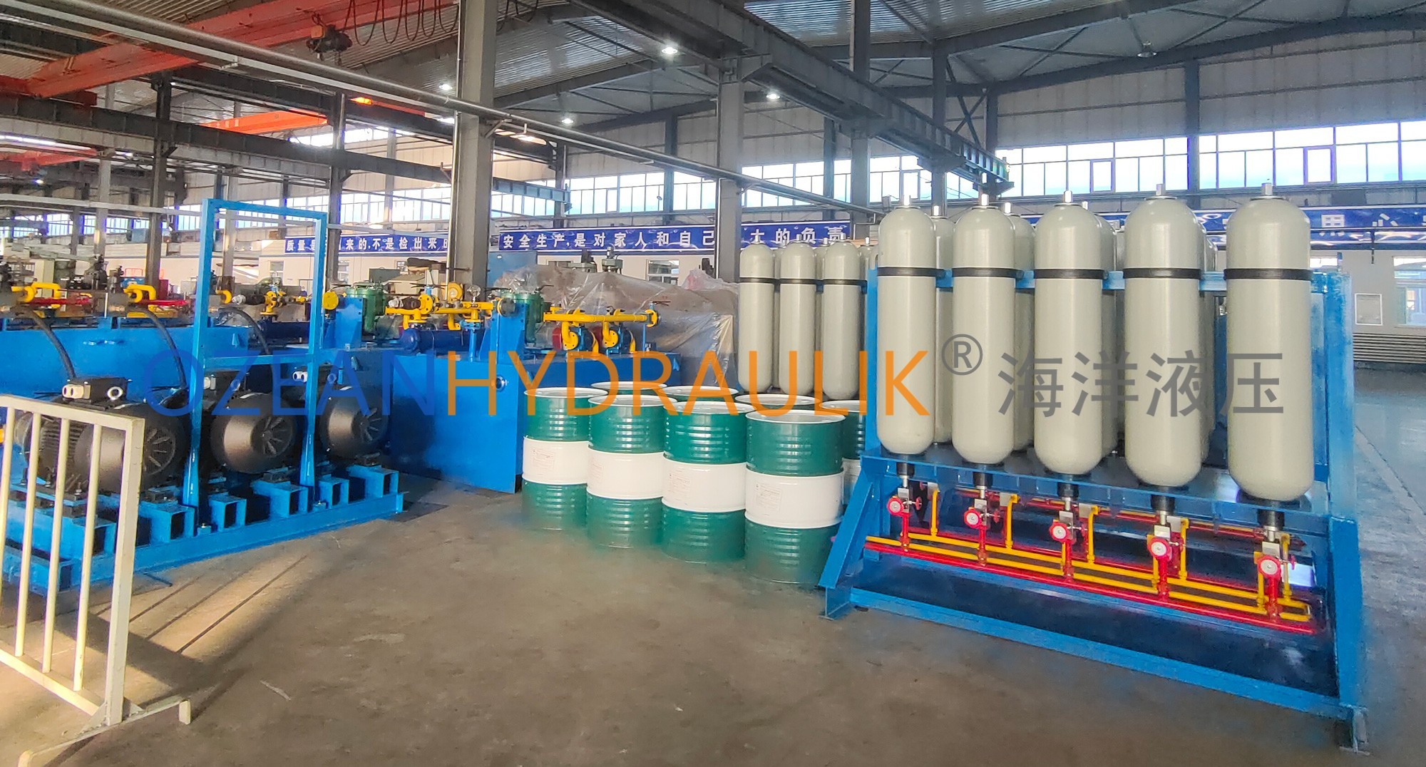
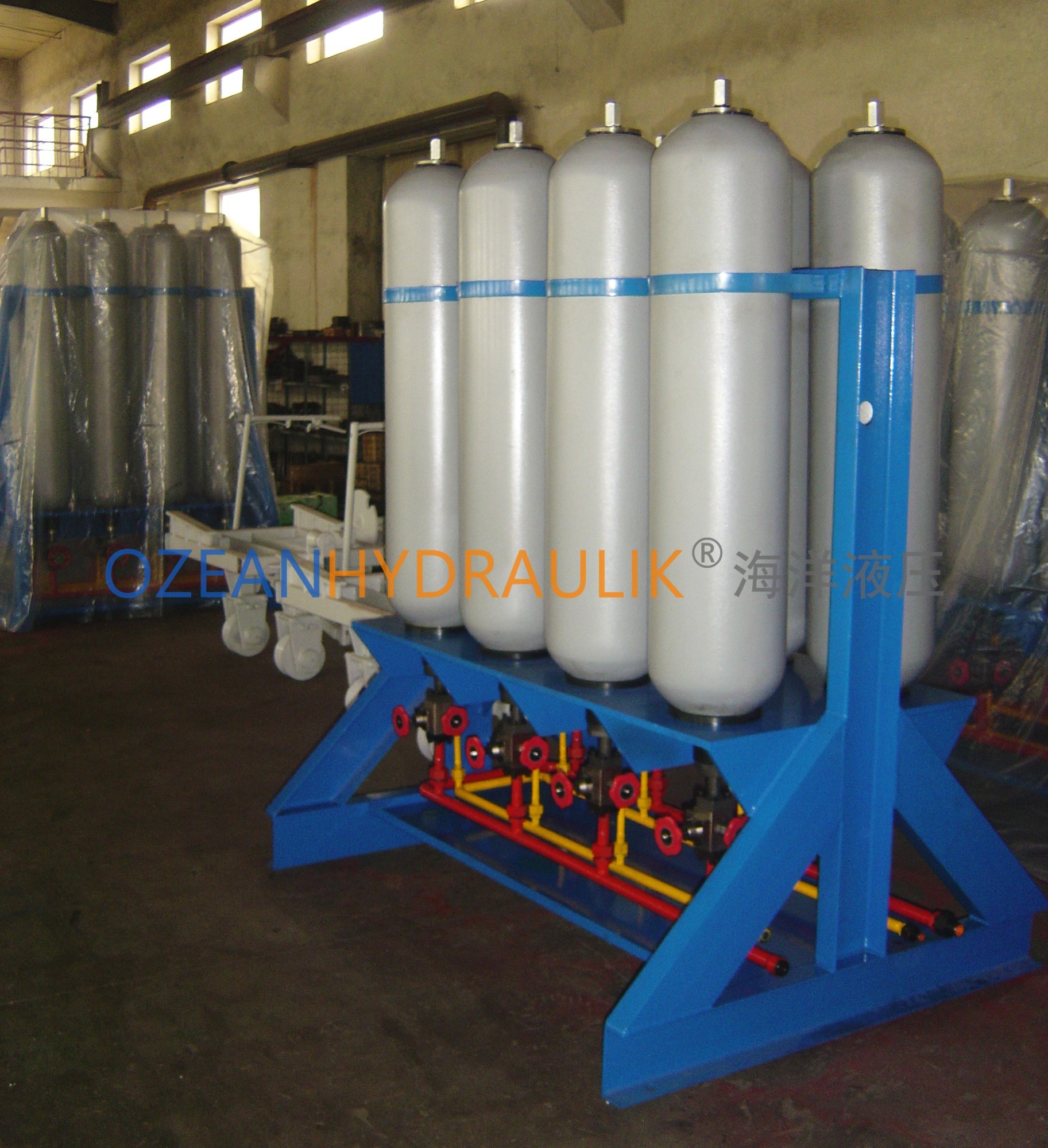
Accumulator Group refers to a combination device in which multiple accumulators are connected in parallel. The accumulator group utilizes the compressibility of gas to store liquid. When the hydraulic system pressure rises, the pressure oil enters the accumulator through the inlet valve, causing the bladder (or piston, diaphragm) to expand and store energy. When the system needs to reduce pressure or release energy, the pressure oil in the bladder (or piston, diaphragm) is discharged through the outlet valve, thereby releasing the stored energy. The accumulator group is widely used in various hydraulic systems, playing a crucial role, especially in balancing system pressure, reducing impact loads, and improving system performance.

Accumulator Group
Equipment Introduction:
Accumulator Group refers to a combination device in which multiple accumulators are connected in parallel.
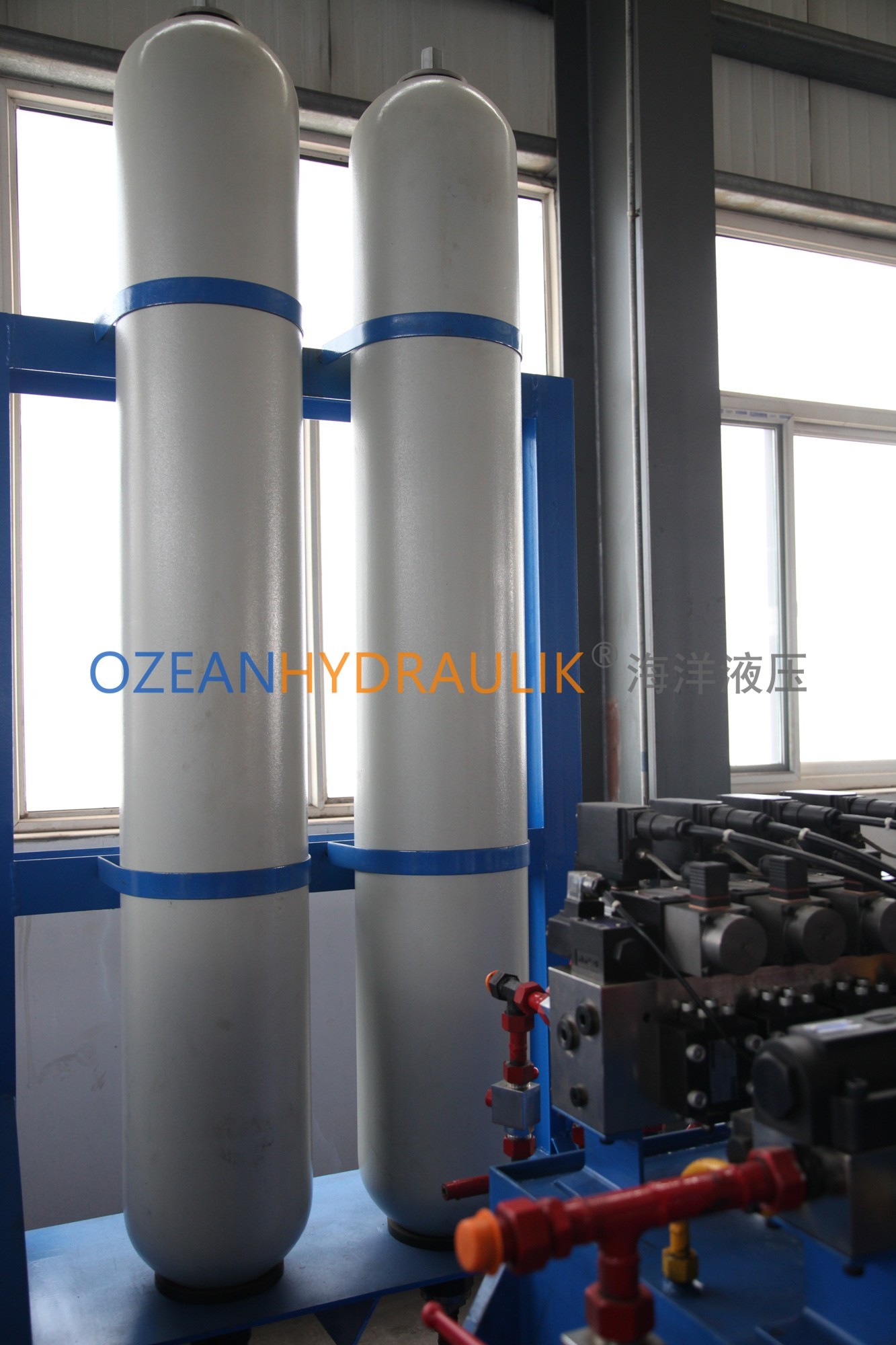
The accumulator group utilizes the compressibility of gas to store liquid. When the hydraulic system pressure rises, the pressure oil enters the accumulator through the inlet valve, causing the bladder (or piston, diaphragm) to expand and store energy.
When the system needs to reduce pressure or release energy, the pressure oil in the bladder (or piston, diaphragm) is discharged through the outlet valve, thereby releasing the stored energy. The accumulator group is widely used in various hydraulic systems, playing a crucial role, especially in balancing system pressure, reducing impact loads, and improving system performance.

Product Description
Blueprints / Drawings
Note: These drawings are for reference only. The final design will be customized based on your requirements.
Outline Drawing

Main Parameter
| Model | Nominal Volume (L) | Design Pressure (MPa) | Dimensions (mm) | Weight (kg) | ||||||||
|---|---|---|---|---|---|---|---|---|---|---|---|---|
| L | L1 | L3 | H | D | D1 | D2 | d4 | 6-d0 | kg | |||
| NXQA-0.4/P-F-Y | 0.40 | 10、20、31.5 | 253 | 135 | 55 | 2.4–0.00.1 | Φ89 | Φ77 | Φ110 | 6-Φ17 | 3 | |
| NXQA-0.63/P-F-Y | 0.63 | 303 | 190 | 3.6 | ||||||||
| NXQA-1/P-F-Y | 1 | 323 | 200 | Φ114 | 5 | |||||||
| NXQA-1.6/P-F-Y | 1.6 | 365 | 251 | 80 | Φ152 | Φ99 | Φ130 | Φ50H9 | 6-Φ17 | 11 | ||
| NXQA-2.5/P-F-Y | 2.5 | 430 | 280 | 14 | ||||||||
| NXQA-4/P-F-Y | 4 | 540 | 390 | 16 | ||||||||
| NXQA-6.3/P-F-Y | 6.3 | 710 | 560 | 22 | ||||||||
| NXQA-10/P-F-Y | 10 | 662 | 490 | 100 | Φ219 | 125 | 160 | Φ65H9 | 6-Φ21 | 39 | ||
| NXQA-16/P-F-Y | 16 | 872 | 700 | 54 | ||||||||
| NXQA-25/P-F-Y | 25 | 1572 | 1000 | 74 | ||||||||
| NXQA-40/P-F-Y | 40 | 1692 | 1520 | 108 | ||||||||
| NXQA-20/P-F-Y | 20 | 675 | 490 | 105 | Φ299 | Φ150 | Φ200 | Φ80H9 | 6-Φ26 | 80 | ||
| NXQA-25/P-F-Y | 25 | 765 | 580 | 90 | ||||||||
| NXQA-40/P-F-Y | 40 | 1045 | 860 | 118 | ||||||||
| NXQA-63/P-F-Y | 63 | 1465 | 1280 | 171 | ||||||||
| NXQA-63/P-F-Y | 63 | 1465 | 1280 | 171 | ||||||||
| NXQA-80/P-F-Y | 80 | 1805 | 1620 | 213 | ||||||||
| NXQA-100/P-F-Y | 100 | 2185 | 2000 | 253 | ||||||||
The above parameters are for reference; customization is available according to specific requirements.
Ready to take your project to the next level?
Trust our experienced team to provide customized solutions for your project. We’re available 24/7 to answer your questions. Contact us now to get started.